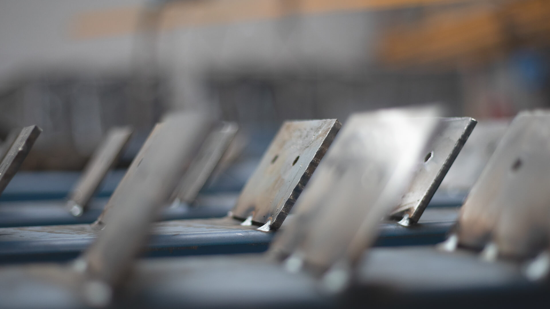
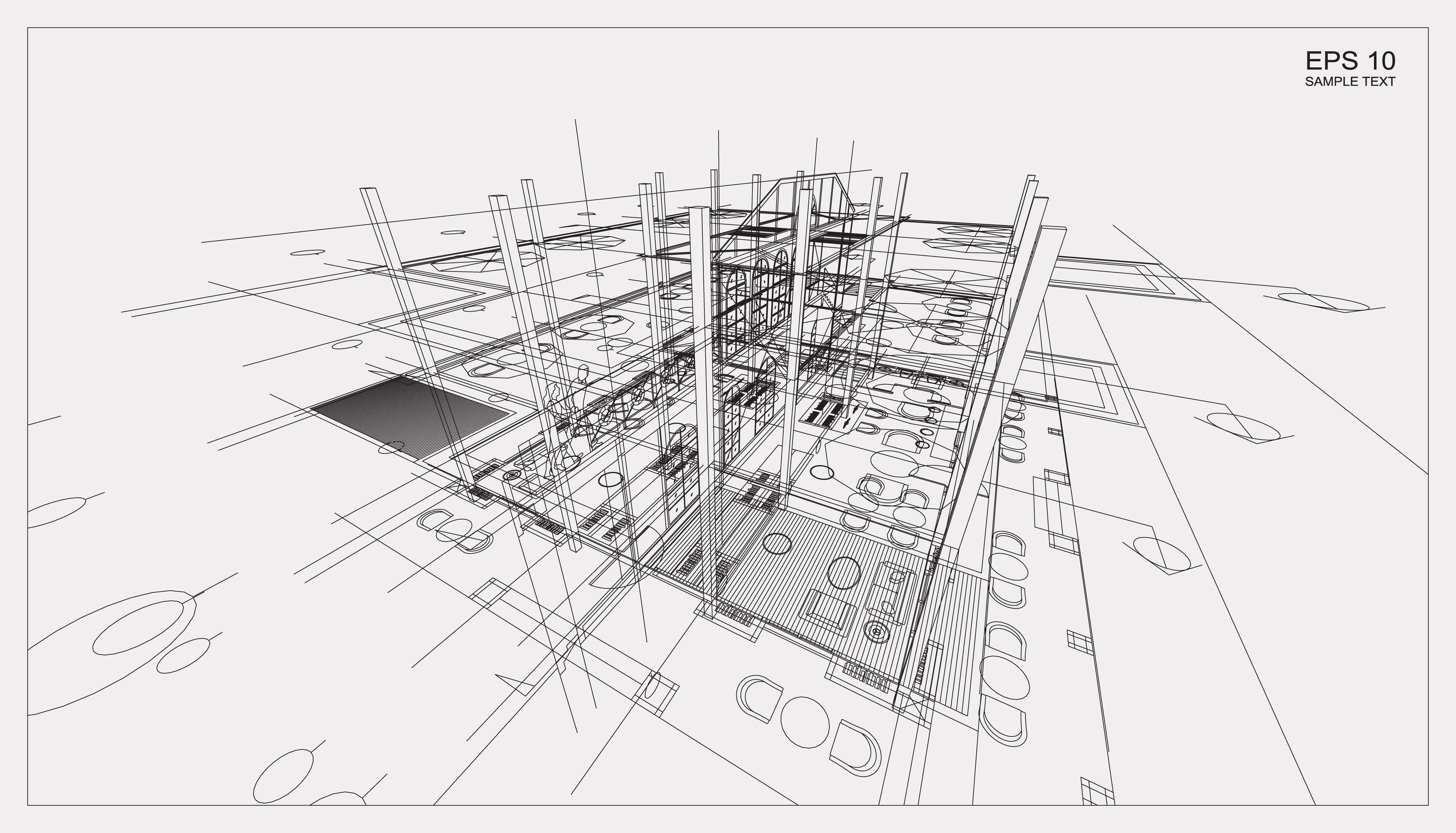
Structural steel drawings illustrate the plans of a building or steel construction.
If you are new to the world of construction but have a project in mind, you might be wondering what you need to know about the planning phase. One of the most useful skills you can learn is how to make sense of structural steel fabrication drawings. While it may seem overwhelming at first, understanding structural drawings is something you can do with a little time, practice and patience. Read on to find out more about what structural steel drawings are used for, and how to read them…
What are structural steel drawings?
Structural drawings refer to engineering plans that layout how a planned building will be erected. Structural drawings provide the construction team with guidance as to the details of the project. In most cases, architectural drawings come before the structural drawings and depending on the particular project, the structural drawings may be based on the architectural drawings.
When it comes to structural steel drawings specifically, the drawings illustrate exactly where the steel materials will be used in the construction. These types of drawings guide the contractors when selecting materials for the project and let them know where each steel structure needs to be placed in the building.
What are the key components of structural steel drawings?
There are a few components that make up structural steel fabrication drawings. These include the building’s elevations, which essentially illustrate the building’s external walls; and the structural plan, which shows the position of foundations, floors and roof, as well as any structural steel elements. These components are very important when it comes to the planning of material quantities such as structural steel.
How do you read structural steel drawings?
When it comes to creating structural steel drawings, the architect and engineer will typically collaborate during this process. To make sense of these drawings, you will need to understand how the scale works to ascertain the dimensions of the building. Several scales may be used, so you will need to take care to interpret them correctly to get a realistic sense of what the final product will look like. The scale type is usually stated on the documents, and it can be helpful to use a scaled ruler to properly interpret the scales on the drawings.
You will also need to become familiar with certain symbols that the engineer will use on the structural plans. Symbols are used in structural steel drawings to save time and depict factors like elevations or sections. Callout symbols are special symbols that are often used in construction to indicate where steel materials should meet.
You may also notice some abbreviations on the plans, which you will need to familiarise yourself with to read the drawings correctly.
How can we help?
At BridgeFab, we offer a range of services and can assist you with your project from start to finish. We use new drafting and imaging technologies to create design layouts, so our process is much more efficient than traditional methods. 3D scanning technology allows us to create 3D models and plan what materials are required in an extremely accurate way.
Our team has worked on a broad range of projects over the years, including hospitals, residential buildings, breweries, churches and shopping centres — if you would like to see some of our previous work, please take a look at our showcase page. If you have a project that you would like started and need assistance with steel processing and fabrication, please don’t hesitate to get in touch so we can discuss our process with you.
To arrange a consultation with us or to request a quote, please don’t hesitate to get in touch or give us a call on (07) 3373 8777. We look forward to assisting you with your project.


